Require circuit diagram for PIC16F630

Microcontroller Topics
Post Reply
GihanAsanka
Sergeant Major
Sergeant Major
Posts: 28
Joined: Mon Aug 15, 2011 4:09 pm

Require circuit diagram for PIC16F630

Post by GihanAsanka » Wed Aug 17, 2011 3:07 pm

Sorry that confuse.
Can you give me working (tested) cc't diagrame for above 16f630 i.c
Thanks

[ Post made via Mobile Device ] Image
Last edited by Neo on Wed Aug 17, 2011 3:15 pm, edited 1 time in total.
Reason: Given a good topic title
User avatar
Neo
Site Admin
Site Admin
Posts: 2642
Joined: Wed Jul 15, 2009 2:07 am
Location: Colombo

Re: Require circuit diagram for PIC16F630

Post by Neo » Wed Aug 17, 2011 4:02 pm

The question isn't clear. Circuit diagram to do what? I'll add some general circuit diagrams if you want to verify the pin arrangements.
1.GIF
1.GIF (8.69 KiB) Viewed 13142 times
2.GIF
2.GIF (11.22 KiB) Viewed 13142 times
Power supply: Standard 7805 arrangement. If you want a better regulator which consumes less power, have a look at SMPS 5V regulator wanted topic.
3.GIF
3.GIF (3.31 KiB) Viewed 13142 times
Can you give me working (tested) cc't diagrame for above 16f630 i.c
We can't involve in designing circuit diagrams just because we are very busy with our day to day work. But we are happy enough to give assistance through the forum when you face issues with your designs.

Working with digital electronics is like playing with building blocks. If you make a stepper motor working with one micro, you can move it to another straight away or with simple modifications. So it's about gathering experience on integrating more blocks. That's it!
GihanAsanka
Sergeant Major
Sergeant Major
Posts: 28
Joined: Mon Aug 15, 2011 4:09 pm

Re: Require circuit diagram for PIC16F630

Post by GihanAsanka » Wed Aug 17, 2011 6:07 pm

Thanks
This is the thing i need (first attached, 1.gif) If i need drive 100LED with 16f630 (acording first attachment) which transister should i use? Instent B547

[ Post made via Mobile Device ] Image
User avatar
Neo
Site Admin
Site Admin
Posts: 2642
Joined: Wed Jul 15, 2009 2:07 am
Location: Colombo

Re: Require circuit diagram for PIC16F630

Post by Neo » Thu Aug 18, 2011 2:06 am

We are back to the same topic we discussed in your post: How to connect PIC16F630 micro to 500 LEDs ;)

I realised that you will have to also consider connecting the LEDs correctly. Can you tell me how you have connected them?

See my update https://robot.lk/viewtopic.php?f=18&t=2709#p8118. There with option 1 which takes only 350mA, you can use one of BC337 (500mA), 2N2222 (or PN2222A) (800mA) or 2N3568 (or PN3568) (500mA). Only thing you need to consider in choosing a transistor is the current which it provides needs to be more than 350mA.

BC547 will not work since it can only provide 100mA. The two transistors you mentioned in your previous post which one can provide 150mA whereas the other is 100mA will also not match.
GihanAsanka
Sergeant Major
Sergeant Major
Posts: 28
Joined: Mon Aug 15, 2011 4:09 pm

Re: Require circuit diagram for PIC16F630

Post by GihanAsanka » Sat Aug 20, 2011 3:30 pm

i am attached my cc't diagrame. I use I test it with 12F675, it work. But when i put this cc't with 16F630 it not work.What shall i do?
I will have to connect 3set as SDC-00195.jpg to my cc't diagrame.
DSC00195.JPG
DSC00195.JPG (151.83 KiB) Viewed 13099 times
DSC00196.JPG
DSC00196.JPG (127.45 KiB) Viewed 13099 times
[ Post made via Mobile Device ] Image
User avatar
Neo
Site Admin
Site Admin
Posts: 2642
Joined: Wed Jul 15, 2009 2:07 am
Location: Colombo

Re: Require circuit diagram for PIC16F630

Post by Neo » Sat Aug 20, 2011 6:32 pm

1st diagram is okay. Who has written the 2nd diagram? Whoever written that doesn't even seems to know the fundamentals of transistors.
GihanAsanka
Sergeant Major
Sergeant Major
Posts: 28
Joined: Mon Aug 15, 2011 4:09 pm

Re: Require circuit diagram for PIC16F630

Post by GihanAsanka » Sat Aug 20, 2011 9:15 pm

what wrong with 2nd diagrame? Pls. Correct it
thankr

[ Post made via Mobile Device ] Image
User avatar
Neo
Site Admin
Site Admin
Posts: 2642
Joined: Wed Jul 15, 2009 2:07 am
Location: Colombo

Re: Require circuit diagram for PIC16F630

Post by Neo » Sun Aug 21, 2011 3:16 am

Do you know about the junction forward voltage or Vbe (This is called bias voltage as well). The junction forward voltage is the voltage applied to the emitter-base junction of a BJT in order to make the base conduct a specified current. For silicon transistors (most common) this is 0.71 V. Have a look at http://en.wikipedia.org/wiki/Transistor ... r_material for other types.

The technique you wanted to use here is called Darlington pair (or just Darlington). A Darlington consists of two transistors. One is a smaller signal transistor and the other is a larger power transistor. The current gain is approximately the product of both transistors' forward current gains. One point to note is that as first transistor's emitter is connected to the base of the second one, the bias voltage required is Vbe1 + Vbe2. If both transistors are silicon type, this will be around 1.4 V (0.7 x 2).

In your circuit, the second transistors base stays at 0 V. So that is not even biased, how you can expect your circuit to work? I don't think this transistor combination has worked for you on a PIC 12F as you said. It is simply impossible.

It is important to learn some basic theory in electronics. That'll be very useful when you are doing some serious work.

Darlington comes as a single transistor (2 transistors in one) or set of Darlington pairs in a single IC called Darlington array. In the topic What are the transistors that can handle high currents, I have mentioned some part numbers of Darlington pairs. If you buy a single ULN2003A IC, you'll be able to drive 7 outputs. Each output is a Darlington pair which can handle up to 500mA which is enough for your application.

If you need to make a Darlington pair yourself, here is the circuit diagram.
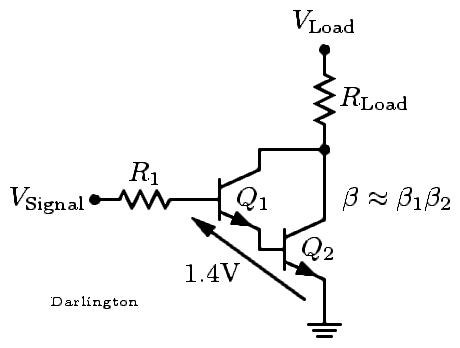
Darlington.png
Darlington.png (4.22 KiB) Viewed 13086 times
RLoad needs to be replaced with your LED set.

It will be easy for you if you try the Darlington transistor TIP120 (2 transistors packed in to one plastic module) or since you have many outputs ULN2003A which has 7 Darlington outputs. See the topic What are the transistors that can handle high currents for information.
GihanAsanka
Sergeant Major
Sergeant Major
Posts: 28
Joined: Mon Aug 15, 2011 4:09 pm

Re: Require circuit diagram for PIC16F630

Post by GihanAsanka » Thu Aug 25, 2011 7:06 pm

Ok thank you .i got more detail above matter.Any way What is the cheepest way use TIP120 or ULN2003 ? Can you give corret diagram with ULN2003 & TIP120

[ Post made via Mobile Device ] Image
User avatar
Neo
Site Admin
Site Admin
Posts: 2642
Joined: Wed Jul 15, 2009 2:07 am
Location: Colombo

Re: Require circuit diagram for PIC16F630

Post by Neo » Fri Aug 26, 2011 3:35 am

Any way What is the cheepest way use TIP120 or ULN2003 ?
Since you have 5 x 100 LEDs, you will need 5 x TIP120 transistors to handle that. But since the requirement is 500 mA per output, you can easily use a single ULN2003A chip which has 7 outputs.
Can you give corret diagram with ULN2003 & TIP120
For TIP120, just replace the BC547 in the first diagram of 2nd post.
ULN2003.gif
ULN2003.gif (10.4 KiB) Viewed 13050 times
Here you can connect other pins of uC to 2B up to 7B to get output from 2C up to 7C respectively. That means you can connect 7 x 100 LEDs you want using this chip. One other thing is, this chip is highly available in Sri Lanka just because people commonly use this.
Post Reply

Return to “Microcontrollers”