How to connect PIC16F630 micro to 500 LEDs

Microcontroller Topics
Post Reply
GihanAsanka
Sergeant Major
Sergeant Major
Posts: 28
Joined: Mon Aug 15, 2011 4:09 pm

How to connect PIC16F630 micro to 500 LEDs

Post by GihanAsanka » Mon Aug 15, 2011 9:14 pm

:clap:

Hi can you help Me...........

I wrote an .asm file for pic16F630 for 7 out puts. It works correctly on my Real Pic simulator. But when I put it in to my CC’t it won't work. I use C1815 and B562 transistor for drive a 500 Leds, when I put single led with 1K resister for each output pin it will blink. Those C1815 & B562 transistors are new parts (newer use before). But same transistor work with 12F675.hex

If any one can tell which transistor should I use for drive above leds?
I attached my "16f630-final.asm file


Please help me
16f630-final.txt
16F630-final.asm
(1.91 KiB) Downloaded 575 times
Thanks
Last edited by Neo on Tue Aug 16, 2011 1:24 am, edited 2 times in total.
Reason: Placed attachment to the post using "Place Inline" button. Added a good topic title.
User avatar
Neo
Site Admin
Site Admin
Posts: 2642
Joined: Wed Jul 15, 2009 2:07 am
Location: Colombo

Re: How to connect PIC16F630 micro to 500 LEDs

Post by Neo » Tue Aug 16, 2011 12:43 am

Hi Gihan

First of all Welcome to ROBOT.LK!!! ???????? ?????????? !!!

The problem is, you are using low current transistors. 500 LEDs is too much to drive with transistors. According to what I have found C1815 is about 150mA. You can use power transistors. But the best option I see for you is Power MOSFETs which can drive quite a lot of current.

Have a look at following FETs.
IRF 510 - ~5A (Aprox. 5 Amperes)
Datasheet - http://www.irf.com/product-info/datashe ... irf510.pdf

IRF 520 - ~9A
Datasheet - http://www.irf.com/product-info/datashe ... irf520.pdf

IRF 540 - ~30A (I think this will be good for you. I remember this was about LKR 50)
Datasheet - http://www.irf.com/product-info/datashe ... rf540n.pdf

Here is a circuit diagram.
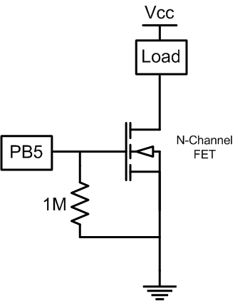
fet.png
fet.png (9.35 KiB) Viewed 10543 times
Keep noted that FETs are more susceptible to static electricity damage. However don't worry too much on this.

A good way to drive an FET is by using a transistor as in following circuit diagram. Keep noted that following circuit will invert the uC output.
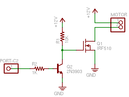
fettrn.png
fettrn.png (1.94 KiB) Viewed 10541 times
Furthermore, if you are using a very high current (say 10A) it would be better to use optocouplers (also known as opto-isolators) in conjunction with Power MOSFETs. This will isolate microcontroller from power side. 4N25 is a good optocoupler for microcontroller applications.

Since it works for one LED nicely, I don't think I'll have to investigate your code.

I would also love to know more about you just as the other members. If you could write a little description about yourself in Introductions, it would be easier for everyone to get to know you better. Our facebook group is at http://www.facebook.com/groups/robot.lk/. Join with that and add all your friends to the group. So we can spread the message faster.


Good luck to you! Don't forget to submit your feedback.
GihanAsanka
Sergeant Major
Sergeant Major
Posts: 28
Joined: Mon Aug 15, 2011 4:09 pm

Re: How to connect PIC16F630 micro to 500 LEDs

Post by GihanAsanka » Tue Aug 16, 2011 2:46 pm

Dear Neo

Thanks for reply

I don't think that is a not answer for my question. because I use same cc't and power pack with Pic12F675 micro controller.
it works correctly. other thing I'm using only 100 LEDs for each out put pins. Totally 500LEDs (100LEDs x 5 outputs)
User avatar
Neo
Site Admin
Site Admin
Posts: 2642
Joined: Wed Jul 15, 2009 2:07 am
Location: Colombo

Re: How to connect PIC16F630 micro to 500 LEDs

Post by Neo » Tue Aug 16, 2011 6:38 pm

I don't think that is a not answer for my question
I'm a bit confused here. Logically Not (Not) = True. So it is "I do think that is answer to my question" ;)
because I use same cc't and power pack with Pic12F675 micro controller. it works correctly.
But this part says, you were able to work it out with a smaller micro. So I will assume that you are not happy with the FET method to drive high currents.
other thing I'm using only 100 LEDs for each out put pins. Totally 500LEDs (100LEDs x 5 outputs)
I understand that. I don't think you are going to make a flip-flop with a micro ;)

Another confusing point for me was this one.
Those C1815 & B562 transistors are new parts (newer use before). But same transistor work with 12F675.hex
So you are saying that you have never used these transistors before. Then again you say, you have used them with 12F675. Can you elaborate please?

You were telling, for a single LED with 1K resistor it worked. If you put two transistors coupled to drive 100 LEDs, it didn't work with PIC16F630.

So is that mean you were able to drive 100 LEDs per I/O pin on 12F675 with the same setup (that means with same transistors)?
SukhdeepMankoo
Lieutenant
Lieutenant
Posts: 92
Joined: Tue Oct 27, 2009 7:50 pm

Re: How to connect PIC16F630 micro to 500 LEDs

Post by SukhdeepMankoo » Wed Aug 17, 2011 4:45 pm

i am not able to understand or you asking about that you do not have enough I/O Ports or you are facing problem with LEDs interfacing with controller.

Do if you like to have more I/O pins, you can have variety of options depending upon what are you trying to do.e.g you can have shift serial to parallel shift register or 8255
User avatar
Neo
Site Admin
Site Admin
Posts: 2642
Joined: Wed Jul 15, 2009 2:07 am
Location: Colombo

Re: How to connect PIC16F630 micro to 500 LEDs

Post by Neo » Thu Aug 18, 2011 3:32 am

Another question is, how did you connect 100 LEDs?
If you have connected them in series, you might need a power supply of ~300V.

Here are two options for you to power 100 LEDs. I have considered following figures for this calculation.
Source voltage: 12
diode forward voltage: 2*
diode forward current (mA): 20*
number of LEDs in your array: 100
*See 5mm LED typical technical data

Option 1:
  • each 1 ohm resistor dissipates 0.4 mW
  • the 220 ohm resistor dissipates 88 mW
  • together, all resistors dissipate 94.4 mW
  • together, the diodes dissipate 4000 mW
  • total power dissipated by the array is 4094.4 mW
  • the array draws current of 340 mA from the source
1.PNG
1.PNG (22.11 KiB) Viewed 10505 times
Option 2:
  • each 100 ohm resistor dissipates 40 mW
  • together, all resistors dissipate 800 mW
  • together, the diodes dissipate 4000 mW
  • total power dissipated by the array is 4800 mW
  • the array draws current of 400 mA from the source
2.PNG
2.PNG (26.98 KiB) Viewed 10505 times
If you connect with option1, it only takes ~350mA. So you'll be able to use transistors that can cope up with it such as BC337 (500mA), 2N2222 (or PN2222A) (800mA), 2N3568 (or PN3568) (500mA).
GihanAsanka
Sergeant Major
Sergeant Major
Posts: 28
Joined: Mon Aug 15, 2011 4:09 pm

Re: How to connect PIC16F630 micro to 500 LEDs

Post by GihanAsanka » Sat Aug 20, 2011 1:55 pm

[ Post made via Mobile Device ] Image
Post Reply

Return to “Microcontrollers”