Sandun, It is good to see you join the discussion. Please read the mentioned topic first to get a clear idea on their project. They use stepper motors so no PID mechanism is required since motor's position can be controlled precisely without any feedback mechanism. It is good to see people try to answer posts but please make extra measures to give accurate answers. Otherwise the damage to the reputation of ROBOT.LK is far too higher than that.
Shenal, Since you are using stepper motors, you don't need to consider PID (Peripheral-Integral-Derivative) method which is used to smoothly control DC/AC servo motors in motor drives.
However, when you use stepper motors, the accuracy is limited to a single rotation (called a step). You can't get accuracy more than that. Anyway, there are stepper motors with lots of teeth (which means each step is a very small movement) which you can use to precise moving.
Since the rod is connected to the motor, the width of two threads in rod really can't matter as long as the stepper motor can precisely turn.
Have a look at this animation to understand how it works.
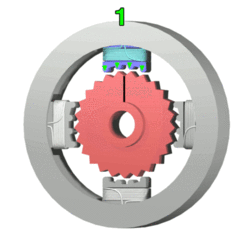
- StepperMotor.gif (77.23 KiB) Viewed 13808 times
Do these two things to find what precision you can get at the moment.
1. Mark a starting point on the rotor and count how many steps you have in a complete rotation.
2. Mark a point on the moving part connected to the rod and measure the distance it travels on one complete rotation.
Do the above to both motors.
With these measures, we can calculate the precision of both direction.
If you read your previous topic, you might see that I mentioned about using another motor or solenoid to control the drawing pen. If you use this, you can precisely mark dots, not lines.
My feeling on the free wheel (bearing) is also not good. You might face practical problems with it on real environment. I suggest you to use a similar motor/rod on that side too.
I know time is against big modifications, but it is good to have a good system rather than a model.
