Page 4 of 6
Re: DCP 650VA UPS circuit
Posted: Fri Aug 06, 2010 8:46 pm
by Nipuna
Thanks guys for Wishing me. I will post my experience later.
I surf the net 30 mins for a day. now i am spending those 30. that's why i got time to post replies here.
Thanks
Re: DCP 650VA UPS circuit
Posted: Sat Aug 07, 2010 12:07 am
by Neo
Hey, we are not going to blame you for coming to ROBOT.LK. As you are one of senior members, we will never forget you. But please concentrate 100% on the exams. After that you can surf 24-hours a day if you want.
Re: DCP 650VA UPS circuit
Posted: Sat Aug 07, 2010 1:11 pm
by Nipuna
Neo wrote:Hey, we are not going to blame you for coming to ROBOT.LK. As you are one of senior members, we will never forget you. But please concentrate 100% on the exams. After that you can surf 24-hours a day if you want.
Thanks Neo I am not saying you are blaming me.
Re: DCP 650VA UPS circuit
Posted: Sun Aug 08, 2010 7:55 am
by Herath
I have been reversing the PCB of the UPS to get some schematics. And I came up something like this,


The resistors are same valued.
The two LM339N s and the LM324 are powered using this power converter.
The output from the diodes has been taken as positive output and the output from the two connected resistors is connected to the ground.(0 Volt).
I am not familiar with this configuration of rectification. And I don't see how this is possible.(Still thinking that I have incorrectly traced the PCB).
Is this possible?. This can be done with 4 resistors. I wonder why they have built it like that.(Lack of high resistors with higher resistance? )

And oh my!, there is a damn lot of resistors (almost 100). And it seems a bit hard to reverse.

Re: DCP 650VA UPS circuit
Posted: Sun Aug 08, 2010 9:07 am
by Neo
Can it be this?
- 83815989.gif (3.8 KiB) Viewed 17099 times
L1, L2 are given power from the two ends of winding and N is the centre tap (Considered 0 volts).
If that is the case it could be something similar to a full-wave rectifier (similar to a bridge rectifier without centre tap) as below.
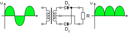
- Fullwave.rectifier.png (19.08 KiB) Viewed 17099 times
Lets follow the discussion.
Re: DCP 650VA UPS circuit
Posted: Sun Aug 08, 2010 9:45 am
by Herath
Yes, that seems to be full wave rectification with two diodes. Thanks.

I checked the both diodes with 1 pin desoldered. And the both diodes are ok. Checked with multimeter. Replace the both LM339N and the LM324N. Replaced an unsure relay driver transistor. Still no luck. I will check further. (Or wait

)
Re: DCP 650VA UPS circuit
Posted: Mon Aug 09, 2010 1:51 pm
by Herath
I think I found the problem with the UPS. It is nothing else, but a dead battery. I borrowed my brothers motor cycle battery for testing after I had nothing to check further on the Mainboard. After connecting that battery. UPS came online with green indicator up. disconnecting A/C switches the UPS to battery. But I did not try the UPS on battery under load since the motor cycle battery was just a 2.5Ah and also I did not want to damage the borrowed item.

Anyway I am thinking of changing the battery. (I have already played with the main circuit. I removed 3 ICs and replaced them with new ICs, with IC bases.
).
I will have to go to Pettah to find a battery. ( I hate those dirty and noisy streets.

)
Re: DCP 650VA UPS circuit
Posted: Mon Aug 09, 2010 3:51 pm
by Neo
Great that you found the problem after some experiments. There is a place near Maya Avenue (Kirulapone) called Magnet Cells who sells a good UPS battery. I remember they were giving me some warranty too. Buying things from Pettah is not always inexpensive. Let us know on how it is going after placing the battery.
Re: DCP 650VA UPS circuit
Posted: Mon Aug 23, 2010 9:05 pm
by Nipuna
Re: DCP 650VA UPS circuit
Posted: Mon Aug 23, 2010 9:31 pm
by Herath
Nipuna wrote:Hey Gays Here is my Story
It's not gays, it's guys. Never mind though, considering it as just a mistake.
Do you remember the component ID of the transistor. It should be something starting with Q.
After I replaced the battery of the unit. it started to work. I did not buy a battery yet. I am gonna buy one in next month. If it's just a transistor i can swap that with the beep driver transistor since I don't want that beep. I already removed the buzzer and replaced that with a LED.


