
And thought to create something.
Then wrote this to make a Digital Clock with only PIC16F628A
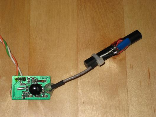
Below are some photos, a video, the circuit diagram and the mikroC code I wrote for this.
Also this clock is not 100% calibrated, so you have to do it manually.
My code is not well commented. So if you got any problem, feel free to ask it here.
- 1.JPG (26.61 KiB) Viewed 18774 times
- 2.JPG (47.28 KiB) Viewed 18774 times
- 3.JPG (34.17 KiB) Viewed 18774 times
- 4.JPG (44.33 KiB) Viewed 18774 times
- Circuit Diagram.jpg (40.01 KiB) Viewed 18774 times
Code: Select all
unsigned short i, DD0, DD1, DD2, DD3, DD4;
char temp=0;

unsigned short mask(unsigned short num) {
 switch (num) {
 case 0 : return 0x40;
 case 1 : return 0x79;
 case 2 : return 0x24;
 case 3 : return 0x30;
 case 4 : return 0x19;
 case 5 : return 0x12;
 case 6 : return 0x02;
 case 7 : return 0x78;
 case 8 : return 0x00;
 case 9 : return 0x10;
 } //case end
}


unsigned int counter = 0;
char second = 0;
char hour = 12;
char minute = 0;

void interrupt(){

     if(PIR1.TMR1IF){
        counter++;
        TMR1H = 0xD8;
        TMR1L = 0xF0;
        if(counter >= 25) {
            counter = 0;
            second++;
            if (second >= 60){
               second = 0;
               minute++;
              if (minute >= 60){
                 minute = 0;
                 hour++;
                if (hour >= 13){
                   hour = 1;
                   /*
                   you can add calibration here,
                   just increase or discrese second or/and minute
                   Ex: minute -= 2
                       second -= 5
                   */
                }

              }
             EEPROM_Write(4,minute);
             EEPROM_Write(2,hour);
            }
        }
        PIR1.TMR1IF = 0;

        if (temp > 0) temp--;

      }
}


void main() {
  CMCON |= 7;
  TRISB = 0b00000000;
  TRISA = 0b00110000;
  PORTB = 0x00;
  PORTA = 0x00;

  hour = EEPROM_Read(2);
  minute = EEPROM_Read(4);

  TMR1H = 0xD8;
  TMR1L = 0xF0;

   T1CON.T1CKPS1 = 1;
   T1CON.T1CKPS0 = 0;
   PIE1.TMR1IE = 1;

   INTCON.PEIE = 1;
   INTCON.GIE = 1;

   T1CON.TMR1ON = 1;


  do {

     if (PORTA.B4 == 1 && temp == 0){

        PORTB.B7=0;
        if (PORTA.B4==0)
        {
         hour++;
         if (hour >= 13) hour = 1;
        }
        else
        {
         minute++;
         if (minute >= 60) minute = 0;
        }

        temp = 12;//doesn't get another button click until a half of second
     }


  DD0 = minute%10;
  DD0 = mask(DD0);

  DD1 = (minute/10);
  DD1 = mask(DD1);

  DD2 = hour%10;
  DD2 = mask(DD2);

  DD3 = (hour/10);
  DD3 = mask(DD3);

  if (counter > 12) DD4 = 1;
  else DD4 = 0;//blick the LED onece a second

  for (i = 0; i<=50; i++) {
      PORTB = DD0;
      PORTA = 1;
      delay_ms(1);

      PORTB = DD1;
      PORTA = 2;
      delay_ms(1);

      PORTB = DD2;
      PORTA = 4;
      delay_ms(1);

      PORTB = DD3;
      PORTA = 8;
      delay_ms(1);

      PORTB = 0xFF;
      PORTA = 0;
      PORTB.B7 = DD4; // turn on/off blicking LED
      delay_ms(1);

      }

  } while(1);          // endless loop
}
Please don't copy paste this on your blog or website, just add a link to this page if you are copying.
Also begginers, please try to learn without just copiyng this.