Help My Project(12CH LED Driver)??

Embedded Systems Topics
User avatar
SemiconductorCat
Major
Major
Posts: 455
Joined: Mon Aug 22, 2011 8:42 pm
Location: currently in hyperspace

Re: Help My Project(12CH LED Driver)??

Post by SemiconductorCat » Wed May 09, 2012 9:31 am

Code: Select all

  do {
    temp_res = ADC_Read(2);   // Get 10-bit results of AD conversion
    PORTB = temp_res;         // Send lower 8 bits to PORTB
    PORTC = temp_res >> 8;    // Send 2 most significant bits to RC1, RC0
  } while(1);
}
Note the 2 instead of 0 there.
By the way as it says , you have to enable it as a input before calling that.
you don't need to write to other registers , that's the beauty of that library call.
It will select internal RC sampling rate, internal Vp as the reference and
left justified.

read the compiled code's assembly listing.

and try it in your manual way too. It's not magic. Library is a tool waiting to be used.
User avatar
SevenZero
Major
Major
Posts: 263
Joined: Sun Nov 01, 2009 8:37 pm

Re: Help My Project(12CH LED Driver)??

Post by SevenZero » Wed May 09, 2012 12:09 pm

you don't need to write to other registers , that's the beauty of that library call.
read the compiled code's assembly listing.
and try it in your manual way too. It's not magic. Library is a tool waiting to be used.
All those above 3 points are misguiding. I'll first point it out and then come to Nandika's questions.

Sem.. stated Using libraries is a good thing. But for a simple thing such as ADC, I wonder what's the use of it. It is just a few registers you need to setup and when you do it, you know completely what is happening.

Calling a library routine and see assembly listing to see what the hell the library call has inserted is a crazy idea. This is not a practice in embedded world. I'm working in the field for last many years :)
If you have to write something in C and and have to see the assembly listing to see what's going on, that is simply time wasting. Take my word, MikroC is not professionally used. It is for hobbyists in the age of 10 to 15 in foreign countries.

HI-TECH C and MPLab C are the ones used for professional embedded development. And from those two, even Microchip recommends HI-TECH C because of its massive optimisation ability.

If you are a person who love electronics, I'm sure you will enjoy the HI-TECH C way. MikroC is good for hobbyists and PC programmers. "Ease of use and beauty of library calls" are something belong to PC world. Not the embedded.

However if you have to work on an embedded OS such as Android, RTOS, Micro Linux, Win CE, etc... you will have to use their API (set of libraries) to do certain things. Especially if you are moving to ARM processors, then it is advantageous to move to OS based embedded development.

But for these little micros where even a tiny OS can't be involved (no use even), it is good to write everything by your own. In few months time, you will have your own written functions to do everything. Then you can directly use these.

I'm coming to your questions now.

The answer Semi has given your questions... I don't know for what questions he has answered :? Looks like he doesn't simply have hands on experience with uCs :?:

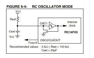
bit 7-6: ADC Conversion Clock
ADC can be thought of a co-unit which can take input from several pins and convert to a digital value. You need to set a clock to this unit so that it can do the processing. ADC can convert a set of pins to their digital values in a single cycle of this clock you set. If you have put a 8MHz oscillator to your uC, then with first setting you can set the ADC to work in 4Mhz. Likewise you can workout the other values. The last one is for the internal RC oscillator built-in to the A/D module. This is not required when you already have a good oscillator fixed to the uC.
10 - Fosc/32 - if main clock is 8 Mhz, this is 250 KHz. I think this is very good.

Some uCs define a lower and upper limit for these. In my experience it is good to have the ADC clock in the range of 100KHz to 200KHz.

2nd question:
bit 7: ADFM
This is to set the justification (right aligned or left aligned) of the converted digital value on 2 registers.
Say the converted value is 11 0101.
If you set this left justified, you will get it as 00 0011 0101.
If you set this right justified, you will get it as 1010 1100 00.
Simple isn't it? When you learn things perfectly, it is very easy.

Here are two of my PIC codes to read ADC. It would be better if you could write your own codes.

Init code. You need to call this function one time at the main().

Code: Select all

// Setup A2D module
void init_a2d(void){
	TRISA  = 0x2F;	//PORTA all pins are input
	ADCON0 = 0x41;	// select Fosc/2 and ADC on
	ADCON1 = 0xC1;	// select left justify result. A/D port configuration 0
	ADON = 1;		// turn on the A2D conversion module
}
Read the channel you want. So if you want to read channel 2, call it as read_a2d(2). Simple as that.

Code: Select all

/* Return an 10-bit bit result */
unsigned short read_a2d(unsigned char channel){

	unsigned short tmpShort;
	channel &= 0x07;		// truncate channel to 3 bits
	ADCON0 &= 0xC5;			// clear current channel select
	ADCON0 |= (channel<<3);	// apply the new channel select

	// Wait till the conversion is completed
	GODONE = 1;
	while (GODONE);

	tmpShort = ADRESH;
	DelayMs(10);
	return ((tmpShort<<8)+ADRESL);
}
The good thing with this code is, you can see what exactly is happening inside rather than wasting on looking at assembly listing by calling 3rd party libraries ;)
User avatar
Nandika
Captain
Captain
Posts: 247
Joined: Sat Oct 15, 2011 11:40 am
Location: Galle-Sri Lanka

Re: Help My Project(12CH LED Driver)??

Post by Nandika » Fri May 11, 2012 2:33 pm

SevenZero wrote:
Init code. You need to call this function one time at the main().

Code: Select all

// Setup A2D module
void init_a2d(void){
	TRISA  = 0x2F;	//PORTA all pins are input
	ADCON0 = 0x41;	// select Fosc/2 and ADC on
	ADCON1 = 0xC1;	// select left justify result. A/D port configuration 0
	ADON = 1;		// turn on the A2D conversion module
}
I have some problems in this code that ZevenZero given befor.
1.

Code: Select all

TRISA  = 0x2F;	//PORTA all pins are input
Is Your description correct?
0x2F,h=101111,b
So,isn't PORTA.F4=Output?

2.

Code: Select all

ADCON0 = 0x41;	// select Fosc/2 and ADC on
Is Your description correct?
0x41,h=1000001,b
So,isn't ADC clock selection=Fosc/32 ?

3.

Code: Select all

ADCON1 = 0xC1;	// select left justify result. A/D port configuration 0
Is Your description correct?
0xC1,h=11000001,b
So,Isn't DTFM=1.therefore,must result format be Right justify?

Thanks All for dedicate your valuable time for me. :oops:
User avatar
SevenZero
Major
Major
Posts: 263
Joined: Sun Nov 01, 2009 8:37 pm

Re: Help My Project(12CH LED Driver)??

Post by SevenZero » Sat May 12, 2012 10:11 pm

1. Refer following image from 16F877A block diagram on datasheet (page number 8)
porta.png
porta.png (7.35 KiB) Viewed 8760 times
Notice that RA4 is not connected to ADC. So it is actually all ADC pins are made as inputs.

2. Nandika, really sorry about the comment. These codes are normally used across many applications and sometimes I forget to correct those comments according to setting.
So,isn't ADC clock selection=Fosc/32 ?
No, it is not.
My settings are,
ADCON0 = 0x41 = 0100 0001b
ADCON1 = 0xC1 = 1100 0001b

My ADCON0 <ADCS1:ADCS0> is 01
My ADCON1 <ADCS2> is 1
So <ADCS2><ADCS1:ADCS0> is 101. This is FOSC/16

3.
So,Isn't DTFM=1.therefore,must result format be Right justify?
You are correct. ADFM is 1 so the result is right justified.
I think right justified is easy insn't it?
The output can be read as ADRESH:ADRESL where Six (6) Most Significant bits of ADRESH are read as ‘0’.
User avatar
Rksk
Major
Major
Posts: 730
Joined: Thu Jan 07, 2010 4:19 pm
Location: Rathnapura, Sri Lanka

Re: Help My Project(12CH LED Driver)??

Post by Rksk » Sun May 13, 2012 1:16 am

Sorry for breaking your discussion here. But I'm asking this again because of anyone didn't answered my question.

Image
as above, it should possible to change clock speed by using a variable resistor for RC oscillator. Am I correct?

[ Post made via Mobile Device ] Image
User avatar
SevenZero
Major
Major
Posts: 263
Joined: Sun Nov 01, 2009 8:37 pm

Re: Help My Project(12CH LED Driver)??

Post by SevenZero » Sun May 13, 2012 9:13 am

as above, it should possible to change clock speed by using a variable resistor for RC oscillator. Am I correct?
Few points.
1. It is a bad approach to have a variable clock on digital electronics. Besides variable resistors are very very jerky which make is completely impossible to set to an accurate point. OSCs that we use for microcontorllers are working in megahertz range which is even make the idea worst.

2. When you adjust the clock, I expect the uC to restart until the clock become stable which is not good.

3. Having a variable clock, there is no way for the programmer to setup an accurate clock within the system which is important. Within the code, if we define as 1 uS, it should be 1 uS. For example, if have to RS232 with a variable clock, this will become worst. It will be impossible to define TIMER interrupts to accurately work.

4. Before you compile your code, you have to set what clock type that you are going to use. This sets CONFIGURATION WORD register (See page 144 of datasheet).

Considering all this, it is not a good idea to me. But I appreciate the way you think on alternatives.
User avatar
Nandika
Captain
Captain
Posts: 247
Joined: Sat Oct 15, 2011 11:40 am
Location: Galle-Sri Lanka

Re: Help My Project(12CH LED Driver)??

Post by Nandika » Tue May 15, 2012 1:26 am

SevenZero wrote:1. Refer following image from 16F877A block diagram on datasheet (page number 8)
The attachment porta.png is no longer available
Notice that RA4 is not connected to ADC. So it is actually all ADC pins are made as inputs.
Thank you...I could understand it. :D (I not used data sheet. :x )
I have another question regarding of this RA4.
What is "Output is open drain type." and Buffer Type="ST" means?(I have highlighted it in flowing image.
PORTA of PIC16F877A.PNG
PORTA of PIC16F877A.PNG (30.66 KiB) Viewed 8753 times
SevenZero wrote: 2. Nandika, really sorry about the comment. These codes are normally used across many applications and sometimes I forget to correct those comments according to setting.
So,isn't ADC clock selection=Fosc/32 ?
No, it is not.
My settings are,
ADCON0 = 0x41 = 0100 0001b
ADCON1 = 0xC1 = 1100 0001b

My ADCON0 <ADCS1:ADCS0> is 01
My ADCON1 <ADCS2> is 1
So <ADCS2><ADCS1:ADCS0> is 101. This is FOSC/16
This problem is still problem. :(
Look,
ADCON0-Fosc (2).png
ADCON0-Fosc (2).png (50.42 KiB) Viewed 8753 times
[I did some mad work in hex to binary conversion before.I used calculator and i forget put 0 front of result for get 8bit,therefore,I understood ADCON0 <ADCS1:ADCS0> is 10 .it means Fosc/32]
By the way, :o
Where is ADCON1 <ADCS2> bit of ADCON1 Register?
No Fosc/16 option in PIC16F877A :?:
SevenZero wrote: 3.
So,Isn't DTFM=1.therefore,must result format be Right justify?
You are correct. ADFM is 1 so the result is right justified.
I think right justified is easy insn't it?
The output can be read as ADRESH:ADRESL where Six (6) Most Significant bits of ADRESH are read as ‘0’.
OK I got it.. :D
Thank you ZevenZero... :) :|
User avatar
SemiconductorCat
Major
Major
Posts: 455
Joined: Mon Aug 22, 2011 8:42 pm
Location: currently in hyperspace

Re: Help My Project(12CH LED Driver)??

Post by SemiconductorCat » Tue May 15, 2012 6:51 am

I'll answer your first question about ST input. SevenZero is experienced with hi-tech C so he'll answer your
question as he get time.

Difference Between ST and TTL.

Here ST means Schematic Trigger. The difference on the ST is ST have a hysteresis on input voltage.
It's useful when you have a noisy input. [ the electrical noise is generated due to the terminal behaviors
of conductors and resistors and it's proportional to root(T*R), if my memory is correct].

TTL input is better to take a input from another logic device, ex SPI interface, or from a logic IC.
Example if you take this pin as a input from a analog multivibrator [built with transistors] then that
input required to be ST, or if you use 4017 Johnson counter to divide and feed to microcontroller
as a input then TTL logic is oky. 555 is working perfectly with TTL standard. Because it
have a internal ST.

To understand the hysteresis see the bellow figure.
Image

it have a threshload voltages. both for high and low. termed as [Vlt Vht]

If you still have a question , how this internally works , I warn you it's little bit complicated.
Image

source : read the wiki page about Schematic Trigger it explains this nicely.


So in the case of TTL ,how to connect a switch to TTL?
Simple , use use a capacitor , and a pull up/down resistor combination. That's the simple workaround that
I suggest. But things are not simple as you think, if you strict to FCC standard then you need to come to
micro-controller through a trigger.I could find these triggers in my old motherboard where it does have a
microswithch where circuit is closed when I close the lid of the computer.


Image

^- Figure . A SMD trigger IC , you could find this on your motherboards.


Open Drain Type Output.
It's same as open collector output type. There are open collector outputs everywhere, where it didn't
build a pull up resistor internally. So you need to pull it up. This is done to save energy.


Bibliography
* Hysteresis In OP AMP circuit : http://www.ecircuitcenter.com/circuits/ ... p_comp.htm
* Schematic Trigger : http://en.wikipedia.org/wiki/Schmitt_trigger
* Open Collector IC's : Op AMP LM339 http://www.ti.com/lit/ds/symlink/lm339-n.pdf
User avatar
SemiconductorCat
Major
Major
Posts: 455
Joined: Mon Aug 22, 2011 8:42 pm
Location: currently in hyperspace

Re: Help My Project(12CH LED Driver)??

Post by SemiconductorCat » Tue May 15, 2012 9:10 am

Here Risk this is a complete hijack , However this point is related to the application which OP builds.
So I would like to explain these facts. Because he is also reading a VR.
1. It is a bad approach to have a variable clock on digital electronics. Besides variable resistors are very very jerky which make is completely impossible to set to an accurate point. OSCs that we use for microcontorllers are working in megahertz range which is even make the idea worst.
Your right with your experience SevenZero, because experience never lies. but it's extract how that device
was engineered to behave. Our ear work in log scale, so volume [as we say VR works in this log scale].

Image

variable resistors are two fold. Linear one and log one.Since because of our radio and tv electronic [sound
electronic] guys the log one is more common. I have this difficulty because it's very harder to find a
linear one. Specially a big one So I hacked a broken multimeter and get it's adjustment controller. It worked
prefect to me.

Nadika: In your application , you need to be careful about this. Try to find a linear one.

For example, if have to RS232 with a variable clock, this will become worst. It will be impossible to define TIMER interrupts to accurately work
Yes , it will be impossible to use the TMR modules. But not configured to internal WDT. WDT is also work
with a RC thing. So even don't expect more accuracy which required by RS232 communication.

But you could still do RS232 communication or even USB communication.With using a external UART chip
with SPI interface.

I'm don't done this already, either I'm not experienced on this.but I didn't feel this impossible to do
RS232 or even USB communications with it. If you want precise timing then I highly discourage using
RC things. For a real time clock like application , it's not suitable, your clock will skip, either you used
a crystal oscillator , even a temperature controlled one you need to calibrate it using a lookup table.

[ I have seen 16FXX chips with a internal RTC real time clock module which is build for this purpose ]


Bibliography
External UART: http://en.wikipedia.org/wiki/16550_UART
RTC : http://ww1.microchip.com/downloads/en/A ... 00582b.pdf
Crystal Oven : http://en.wikipedia.org/wiki/Crystal_oven
User avatar
SevenZero
Major
Major
Posts: 263
Joined: Sun Nov 01, 2009 8:37 pm

Re: Help My Project(12CH LED Driver)??

Post by SevenZero » Tue May 15, 2012 12:23 pm

Here ST means Schematic Trigger
It is actually called Schmitt trigger.
This problem is still problem. :(
Looks like you are referring a wrong datasheet. Have a look at this one.
http://ww1.microchip.com/downloads/en/d ... 39582b.pdf
adc.jpg
adc.jpg (62.22 KiB) Viewed 8742 times
Post Reply

Return to “Embedded Systems”