Cherry Blossom
Mini-sumo is a robotic competition class being promoted out of Seattle by Bill Harrison of the
Seattle Robotics Society. The robots are constrained by a 10cm square size and a 500gm weight limit. They can't destroy the playing ring or other robots, but pretty much anything else goes.
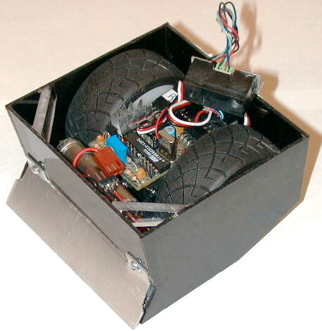
- Mini-Sumo.jpg (39.88 KiB) Viewed 8083 times
My mini-sumo uses the Atmel 90S2313 processor, AvrX and a couple of extra drivers for servos, gearhead motors and proximity sensor (sharp GP2D02). Everything is done in software. Timer0 is used to drive the high speed PWM logic (150khz interrupt rate) and Timer1 drives the system clock (2400/sec).
Here are the schematics, in GIF format, at 300dpi, suitable for printing on a standard sheet of paper.
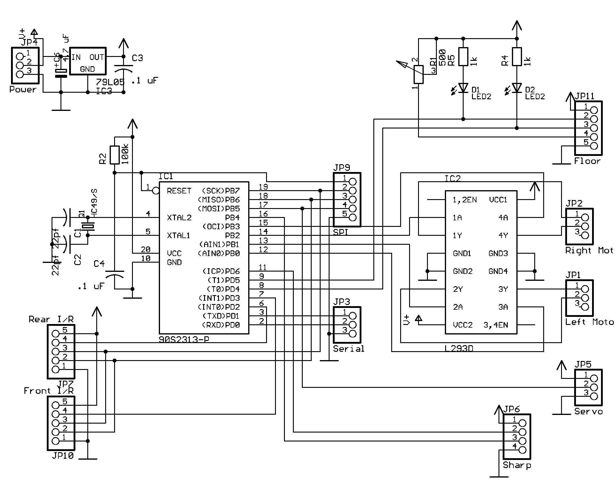
- mini-sumo.gif (55.69 KiB) Viewed 8083 times
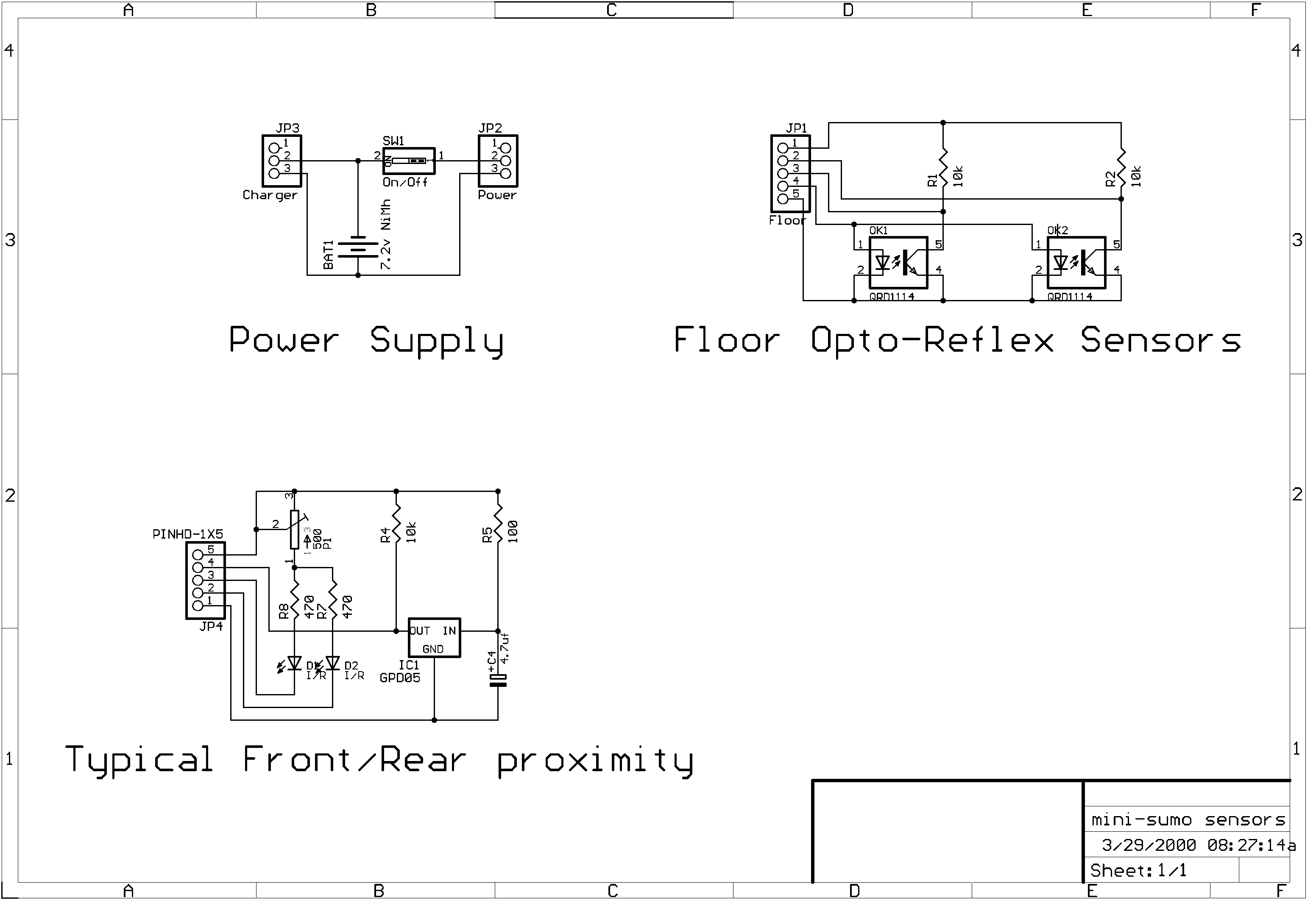
- mini-sumo sensors.gif (58.93 KiB) Viewed 8083 times
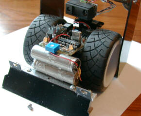
The base is cut from sheet aluminium. The gear head motors are standard R/C servos, gutted and cut on my table saw (!) to allow them to mate together. This allowed me room for some fat racing tires, rather than the skinny O-ring tires typically found on mini-sumo bots.
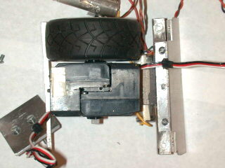
- MotorsOnBase.jpg (17.81 KiB) Viewed 8083 times
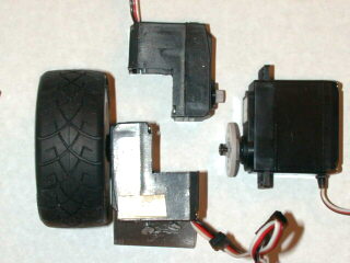
- Motors.jpg (15.84 KiB) Viewed 8083 times
For reasons lost in antiquity, I chose to put one Sharp GP2D02 proximity detector on another servo and scan the playing field for other bots to attack. I had to use a sub-micro servo in order to get the sensor low enough to detect other bots. It turns out that most are no taller than their drive wheels, about the height of my bot.
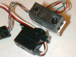
- Sensor1.jpg (17.86 KiB) Viewed 8083 times

- Sensor2.jpg (14.98 KiB) Viewed 8083 times
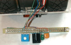
The next challenge was to make the controller small enough to fit between the wheels. The motor driver is an L293 dual H-bridge driver (below the heat-sink). The other parts are the playing ring edge detectors and 5v regulator.
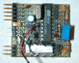
- CPU.jpg (20.64 KiB) Viewed 8083 times
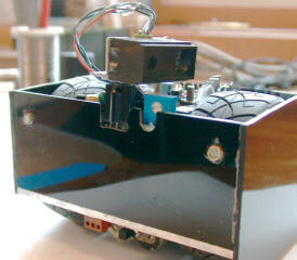
Finally, I had to fit in 6 batteries and the edge detector. Four batteries fit on the bottom just fine.
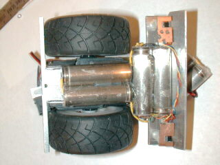
- Batteries.jpg (17.78 KiB) Viewed 8083 times
The other two are stuffed in front of the CPU board.
- FronViewWithCoverOff.jpg (15.03 KiB) Viewed 8083 times
To prepare for the Northwest Sumo contest, held May 15 at the SRS, I added a rear proximity detection system. It consisted of a 40khz I/R receiver (I dunno what brand or make since I gutted it from a parking proximity detector for a car) and two I/R LEDs. I drove the LED's with two spare output pins from the 2313 and checked the state of the detector with a spare input pin. Actually, the code is set up to check a front detector as well, but I did not have time to finish that circuit board.
- RearProximitySensor.jpg (14.02 KiB) Viewed 8083 times
The sensor it the black blob to the (stage) left of the trim pot.
- ProximityCircuitBoard.jpg (11.37 KiB) Viewed 8083 times
Drivers.asm was updated with a third process that managed driving the LED's and decoding the sensor output. The interrupt driver has a clever 9 clock cycle algorithm that drives the left or right LED at 41khz (1/4 the interrupt rate). Note: with the rear near target detection code loaded there is not enough room for the mini monitor. See SumoBot.asm for #defines needed to control which processes are loaded for debugging.
Here is the Sumobot code targeted to the IAR 1.4 assembler: sumobot.zip.
SumoMon.asm - Mini-Monitor for controlling the bot. It is a slim version of the monitor found in the AvrX code. I needed to make it as light as possible in order to shoehorn it into the 2313
Hardware.inc - Include file describing the bot's hardware configuration
Drivers.asm - Contains the heart of the mini-sumo: targeting and boundary avoidance. The targeting has embedded in it the driver for the Sharp GP2D02 sensor and a positioning algorithm for the micro-servo. There is a high speed interrupt handler that manages two channels of PWM and the actual servo pulse formation.
SumoBot.asm - Top level hardware and software initialization
eeprom.asm - Targeting angles and motor drive values
registers.inc - Register definitions
makefile - Instructions on how to assemble the pieces
Serialio.asm - Serial drivers for the monitor.
To build the software you need the Avrx files, the IAR assembler, v1.30 and the following scripts:
build.bat - Batch file to assemble and link the files
debug.xcl - Link command file for debug and hex output
eep.xcl - Link command file for generating the EEPROM output
Courtesy:
Larry Barello


 minisumo.zip