While working on my new robot, Dilbert II, I was trying to figure out a better way to implement line following. Traditional line followers typically use two sensors, one on each side of the line. When the robot veers off to one side or another, the sensor is triggered and changed the direction of the robot. This on-off behaviour is clearly seen with line followers that wiggle back and forth while they run down the line. In all my floor sensor projects I used inexpensive photo-reflexive detectors from Digikey, #QRD1114QT-ND
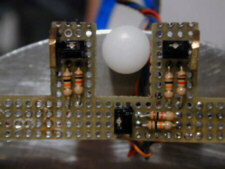
The photo, below, shows the centerline sensors on Dilbert. The two outer sensors are a bit more than ¾” apart so that they straddled the “line” of the 1999 Robothon Line Following Contest.
- dscn0447.jpg (14.12 KiB) Viewed 3889 times
While working on my new robot, Dilbert II, I was trying to figure out a better way to implement line following. Traditional line followers typically use two sensors, one on each side of the line. When the robot veers off to one side or another, the sensor is triggered and changed the direction of the robot. This on-off behaviour is clearly seen with line followers that wiggle back and forth while they run down the line. In all my floor sensor projects I used inexpensive photo-reflexive detectors from Digikey, #QRD1114QT-ND
The photo, below, shows the centreline sensors on Dilbert. The two outer sensors are a bit more than ¾” apart so that they straddled the “line” of the 1999 Robothon Line Following Contest.
- dscn0443.jpg (12.37 KiB) Viewed 3889 times
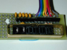
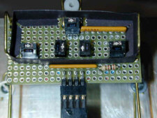
In an attempt to overcome the second problem (one that affected Dilbert as well) I rebuilt the sensor board with sockets. In this experiment I also separated the left and right branch detectors so that they wouldn’t be affected by the emitters of the centre sensors. It turned out that by using sockets the sensors “matched” each other very well. In any case, sockets made it much easier to swap out sensors until I had a nicely matched set. However I still had difficulties with the signal from the centre sensor: it seemed that the right and left centre emitters were flooding the centre detector so that it always was seeing “white”.
- dscn0444.jpg (13.9 KiB) Viewed 3889 times
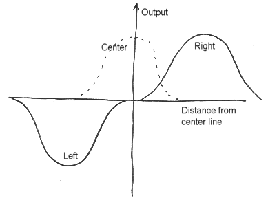
While fighting with the configuration of the detectors I noticed that the left and right centre detectors, alone, separated by ¼”, and oriented so that the emitter (the light portion of each detector) were to the inside, seemed to do a very good job of differentially detecting the centre line. That is, when the line was centred, both read low. When the line moved either left or right, the corresponding sensor would register a signal. So, I tried simply subtracting the A/D value of the left sensor from the right sensor. It turned out to work great. With just two sensors and A/D channels I get a very high resolution error signal for feeding into the line following algorithm. The following is a hand drawing illustrating the signal I get from just two sensors.
- image009.png (7.51 KiB) Viewed 3889 times
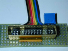
The only thing left to do was to figure out how to tell when the centreline disappeared, since in the line maze contest one could run into a T intersection. I solved that by putting in the centre sensor, again, but moved it forward so it’s emitter wouldn’t interfere with the line following sensors.
- dscn0448.jpg (17.29 KiB) Viewed 3887 times
In order to maximize the range of offset that I could read, I needed to adjust the distance of the sensors from the floor. Since the sensors are so unfocused to begin with, moving them farther from the floor caused the return signal to get soft. I finally settled on a distance that gave me roughly 1” of total sensing area (+/- ½”) and little dead band in the centre. I used my favourite floor sensor hardware to mount the sensors on Dilbert II: 1/16” brass wire. The wire force fits through the holes in the proto board so I can adjust it up and down as needed.
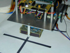
- dscn0449.jpg (14.66 KiB) Viewed 3887 times
A side benefit of the differential detection method is that I don’t need to calibrate the sensors! The absolute signal is cancelled out and all I see is the difference. The range of differences will vary with the absolute range, but for the conditions I have seen so far, it has not been a problem.
Now, with the hardware in place I was ready to implement a line-tracking algorithm. Simply put, I set a forward velocity in my robot, read the line sensor, scale the output by some factor and differentially added it to the current position, thus turning the robot slightly left or right. So, if the robot was a bit off to the left, I added the output of the sensor routine to the left wheel position and subtracted it from the right.
Code: Select all
/*+ -----------------------------------------------------------------
    int GetLineTrackInfo(int scale)

    Passed: Integer scale factor XX.XX
    Returns: 8.8 number from 0.00 to +/- Scale
    Note:   10 bit ADC value, hence divisor of 0x3FF
-*/
int GetLineTrackInfo(int scale)
{
    return ((long)(ADC_Channel(LEFTLINE) - ADC_Channel(RIGHTLINE)) * scale) / 0x3FF;
}

Since Dilbert II has acceleration control, just setting a velocity doesn’t mean the robot is moving at that speed.  So, rather than just stuffing the offset into the wheel position, as I mentioned above, I looked at the actual velocity of the wheels and used that as the scale factor:  In the snippet, below, I use the actual velocity of the left wheel, modify it by a factor, and pass that to the line following routine.

        // Adjust track based upon actual velocity, not set point velocity, so that
        // the robot can get aligned while accelerating...

        d = GetLineTrackInfo(Left.Velocity/FloorData.iFloorScale);
        AddToPosition(&Left,   d);  // Bias drive to correct error
        AddToPosition(&Right, -d);

Finally, I needed some code to tell when the signal from the center sensors was valid.  The simplest thing to do was to use a fixed threshold and the ‘OR’ function: If any sensor of the triad detected the line, I returned valid line

    // Hysteresis too hard for center group.  Just use simple logic:
    // if any are high, then just call the group high.

    if (ADC_Channel(LEFTLINE) > FloorData.iThresholdLow ||
        ADC_Channel(CENTERLINE) > FloorData.iThresholdLow ||
        ADC_Channel(RIGHTLINE) > FloorData.iThresholdLow )
        Sensor.b.center_present = TRUE;
    else
        Sensor.b.center_present = FALSE;
The above algorithms implement a variation of the PID algorithm with respect to line following. The error signal from GetLineTrackInfo() is, very roughly, proportional to the distance off center (well, except at the extremes). That makes for the “P” term. Since the error is added to the drive position, errors are accumulated, or integrated: that makes for the “I” term. PI control is very common in simple velocity control systems and it works quite well for Dilbert II. When turning to a new line, he is rarely dead on center, yet when forward motion starts, Dilbert practically snaps to attention dead on center of the line and tracks very true afterwards.
Courtesy:
Larry Barello
