AC + DC Circuts Help

Electronics & Electrical Engineering Topics
Post Reply
GihanAsanka
Sergeant Major
Sergeant Major
Posts: 28
Joined: Mon Aug 15, 2011 4:09 pm

AC + DC Circuts Help

Post by GihanAsanka » Fri Aug 10, 2012 4:55 pm

Dear Friends

I make these circuits as per diagram. Please see attached picture.
This indication 4LEDs working properly.
Pic IC & Transistor Section is Working Correctly.
But when I give 230V to This BT138 triac Section, No any out put from triac.
Please help me resolve this problem.
pic+4output.jpg
pic+4output.jpg (16.66 KiB) Viewed 8552 times
User avatar
Rksk
Major
Major
Posts: 730
Joined: Thu Jan 07, 2010 4:19 pm
Location: Rathnapura, Sri Lanka

Re: AC + DC Circuts Help

Post by Rksk » Sat Aug 11, 2012 1:44 pm

It may be a wrong pin connection. Please check your diagrame with below diagrames.

Image

Image

[ Post made via Mobile Device ] Image
GihanAsanka
Sergeant Major
Sergeant Major
Posts: 28
Joined: Mon Aug 15, 2011 4:09 pm

Re: AC + DC Circuts Help

Post by GihanAsanka » Sat Aug 11, 2012 3:01 pm

Thanks for reply RKSk

But i need that circuts use with transformer. as my hand drowing diagramme
User avatar
Rksk
Major
Major
Posts: 730
Joined: Thu Jan 07, 2010 4:19 pm
Location: Rathnapura, Sri Lanka

Re: AC + DC Circuts Help

Post by Rksk » Sat Aug 11, 2012 3:35 pm

GihanAsanka wrote:Thanks for reply RKSk

But i need that circuts use with transformer. as my hand drowing diagramme
Problem is there. you have to connect the ground (-) of the circuit with neutral wire(which connected to LED).

[ Post made via Mobile Device ] Image
GihanAsanka
Sergeant Major
Sergeant Major
Posts: 28
Joined: Mon Aug 15, 2011 4:09 pm

Re: AC + DC Circuts Help

Post by GihanAsanka » Sat Aug 11, 2012 6:28 pm

Rksk wrote:
GihanAsanka wrote:Thanks for reply RKSk

But i need that circuts use with transformer. as my hand drowing diagramme
Problem is there. you have to connect the ground (-) of the circuit with neutral wire(which connected to LED).

[ Post made via Mobile Device ] Image

If do like this, it will be ok
5-way-AC-flashe.jpg
5-way-AC-flashe.jpg (54.94 KiB) Viewed 8521 times
User avatar
TRONICLK
Captain
Captain
Posts: 140
Joined: Fri Oct 12, 2018 2:04 am
Contact:

Re: AC + DC Circuts Help

Post by TRONICLK » Sun Aug 12, 2012 6:31 am

Gihan,

First of all, you must understand that there are proper ways to handle electronics. According to theory, you must never ever mix up DC side with 230VAC as you did. It could be too dangerous. So you will have to use opto-isolators to separate the DC side from AC. Have a look at the following diagram with BT138 Triac.
1.jpg
1.jpg (15.03 KiB) Viewed 8511 times
Notice that MOC3081 isolates the DC side from AC here. These types of opto-isolators are called Zero-cross Optoisolator Triac Drivers.

*Note that the 0.01 cap is a 400V one.

Have you ever heard of SSR or Solid State Relays. These types of relays have this functionality in-build. However, those are on the expensive side at the moment.
GihanAsanka
Sergeant Major
Sergeant Major
Posts: 28
Joined: Mon Aug 15, 2011 4:09 pm

Re: AC + DC Circuts Help

Post by GihanAsanka » Sun Aug 12, 2012 3:48 pm

TRONIC.LK wrote:Gihan,

First of all, you must understand that there are proper ways to handle electronics. According to theory, you must never ever mix up DC side with 230VAC as you did. It could be too dangerous. So you will have to use opto-isolators to separate the DC side from AC. Have a look at the following diagram with BT138 Triac.


OK Thanks Dear TRONIC.LK.

I know Thats very dangerous. But I show 90% equal circuts from "Seneth - Sipnena" magazine in 1993. pls see the attachment.
They mixed ac & Dc side.
sipnena.jpg
sipnena.jpg (23.1 KiB) Viewed 8497 times
https://robot.lk/images/smilies/icon_e_sad.gif
User avatar
TRONICLK
Captain
Captain
Posts: 140
Joined: Fri Oct 12, 2018 2:04 am
Contact:

Re: AC + DC Circuts Help

Post by TRONICLK » Sun Aug 12, 2012 10:01 pm

Gihan,

I didn't say that you can't do it. Theoretically it is correct but too dangerous for a user such as you. When I advise as a person who has years of experience in electronics, I can't just let you go and get your hands burned :)

Since you are insisting on correcting the circuit, I'm going to tell you how to sort this out. But the risk is completely on to you. So please take extra care on handling this.
Triac driver.jpg
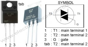
Triac driver.jpg (29.07 KiB) Viewed 8487 times
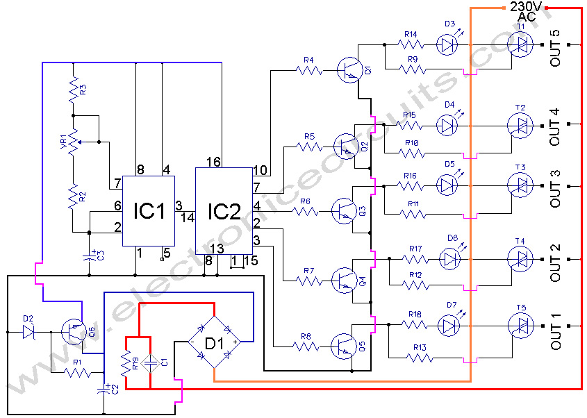
So first thing is to connect the Live wire (230VAC) only to the Triac. Then connect both Neutral and ground of the DC side to be the same. Remove those unnecessary diodes connected from Live to the transistor. In other words, change the circuit to be with same wiring as on the picture I attached above. I'm sure it will work now, but this is not the best way as said before ;)
Post Reply

Return to “Electronics & Electrical Engineering”