Here is a simple, versatile project which indicates the level of water and automatically controls it by using PIC Microcontroller. The Water Level Sensing Section senses the level of water in the tank and sends it (wireless) to the Receiver Section. Receiver Section is connected to the Controlling Section, which process the received information and produces visual, sound indications and controls the operation of the motor whenever required. The project is divide into 4 sections.
1. Power Supply Section
Power Supply section provides required supply for Receiver and Controlling modules. Receiver module requires +5V power supply. Controller module requires +5v and +12v supply. Circuit Diagram:
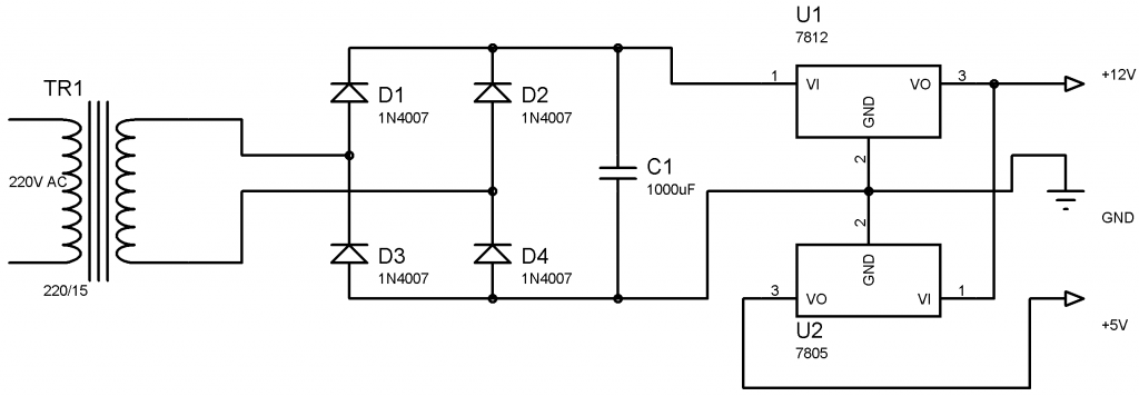
- 1.png (25.35 KiB) Viewed 3575 times
2.Water Level Sensing Section
Receiver Module is made of with HT12D decoder and ASK RF receiver.The data transmitted by the Sensor module is received by this module and is given to the Controlling Module.
4. Controlling Section
Circuit Diagram :
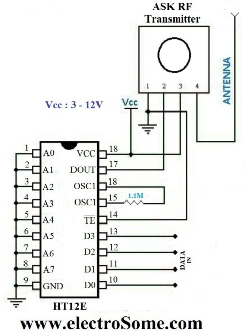
- ASK RF Transmitter
- 2.jpg (65.57 KiB) Viewed 3575 times
Level Sensor module is made of with HT12E encoder and ASK (Amplitude Shift Keying) RF transmitter. This circuit can be drive using 9V battery. This circuit is placed near the Water Tank and connected to the tank as show in the figure below.
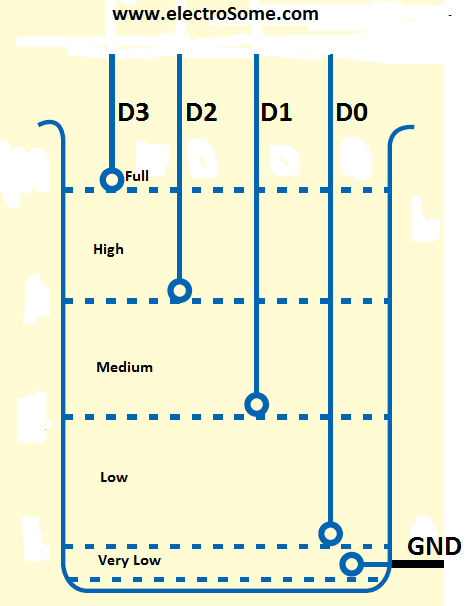
- 3.png (6.23 KiB) Viewed 3575 times
3. Receiver Section
Circuit Diagram:
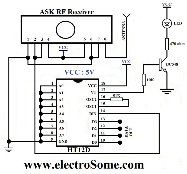
- ASK RF Receiver
- 4.jpg (69.93 KiB) Viewed 3575 times
Receiver Module is made of with HT12D decoder and ASK RF receiver. The data transmitted by the Sensor module is received by this module and is given to the Controlling Module.
4. Controlling Section
Circuit Diagram :
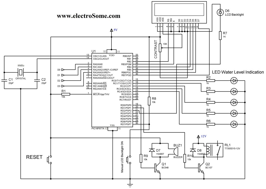
- Water Level Indicator Controller using PIC Microcontroller
- 5.jpg (91.77 KiB) Viewed 3575 times
The soul of the Controlling Section is PIC16F877A. It process the data given by the Receiver Section. LCD Display, LED Indications and Motor status are updated according to the data.
Working
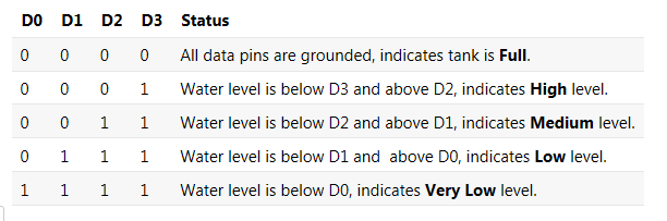
For the transmission and reception of data we have used Holtek encoder-decoder pair of HT12E and HT12D. Both of them are CMOS ICs working voltage ranges from 2.4 to 12v. The oscillator resistances are chosen according to the datasheet. When water level raises, the data pins of the encoder will be grounded corresponding to the level of water, which will be transmitted to the Receiver via ASK RF module. The received data is decoded by the decoder HT12D. LED on the receiver indicates that it is receiving data. Then the data is given to the PIC for processing.
- 6.png (10.36 KiB) Viewed 3575 times
When the water level becomes Very Low, the motor will turned ON, buzzer sounds and the LCD backlight will automatically turned ON for 5 seconds. After this, when the water level reaches Full level, the motor will automatically turned OFF, buzzer sounds and the LCD backlight will automatically turned ON for 5 seconds. During normal operation you can manually turn on LCD backlight by pressing the Push button switch. The LCD indicates the Level of water (‘Very Low’, ‘Low’, ‘Medium’, ‘High’,'Full’) and the status of the motor (‘ON’ or ‘OFF’). The LED bar will also indicate the level of water.
Article courtesy of
electrosome.com
