A Digital Thermometer can be easily constructed using a PIC Microcontroller and LM35 Temperature Sensor. LM35 series is a low cost and precision Integrated Circuit Temperature Sensor whose output voltage is proportional to Centigrade temperature scale. Thus LM35 has an advantage over other temperature sensors calibrated in Kelvin as the users don’t require subtraction of large constant voltage to obtain the required Centigrade temperature. It doesn’t requires any external calibration. It is produced by National Semiconductor and can operate over a -55 °C to 150 °C temperature range. Its output is linearly proportional to Centigrade Temperature Scale and it output changes by 10 mV per °C.
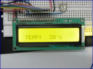
- 1.jpg (17.86 KiB) Viewed 2554 times
The LM35 Temperature Sensor has Zero offset voltage, which means that the Output = 0V, at 0 °C. Thus for the maximum temperature value (150 °C), the maximum output voltage of the sensor would be 150 * 10 mV = 1.5V. If we use the supply voltage (5V) as the Vref+ for Analog to Digital Conversion (ADC) the resolution will be poor as the input voltage will goes only up to 1.5V and the power supply voltage variations may affects ADC output. So it is better to use a stable low voltage above 1.5 as Vref+. We should supply Negative voltage instead of GND to LM35 for measuring negative Temperatures.
This article only covers the basic working of Digital Thermometer using PIC Microcontroller and LM35, and uses 5V as Vref+. If you want more accurate results it is better to select Vref+ above 2.2V. I suggest you to use MCP1525 IC manufactured by Microchip, which will provide precise output voltage 2.5.
Circuit Diagram
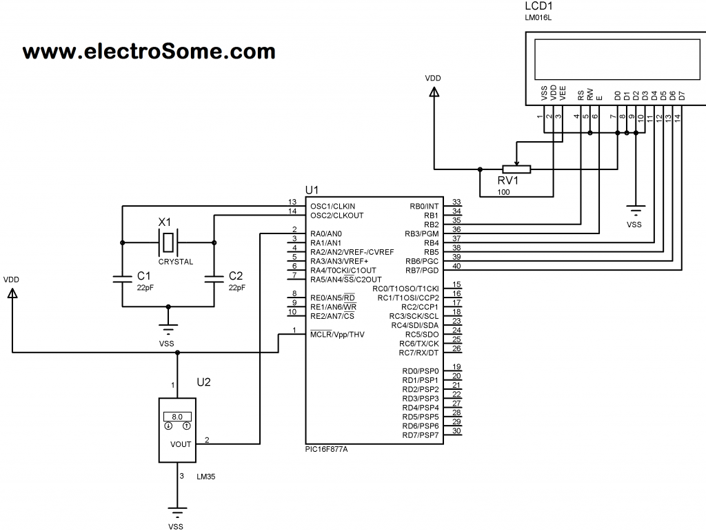
- Digital Thermometer using PIC Microcontroller and LM35 Circuit Diagram
- 2.png (110.68 KiB) Viewed 2554 times
Note: VDD and VSS of the pic microcontroller is not shown in the circuit diagram. VDD should be connected to +5V and VSS to GND.
Article courtesy of
electrosome.com
